http://egg.uchc.edu/injection
Comments on this manual. An
acrobat version is also available
Latest revision: 3/5/99 - frog microinjection
Table of Contents
Introduction
Microinjection
B. Preparation of the microinjection slide
D. Microinjection of frog eggs
Microinjection Equipment and Supplies
D. Starfish and starfish supplies
This manual describes a method for microinjection of oocytes using quantitative techniques initially used by Pierre de Fonbrune in the 1930's to inject amoeba (see De Fonbrune, 1949). These techniques were developped and applied to eggs by many investigators, in particular Hiramoto (1962), Kiehart (1982), Kishimoto (1986), and Terasaki and Jaffe (1993). A screw-controlled syringe is used to fill and expel solutions from the tip of the micropipet. However, the syringe cannot be used for regulating the injection volume directly, since displacements of the syringe are in the range of fractions of a milliliter, while picoliter volumes are injected. To solve this problem, a small droplet of mercury is back loaded then pushed to the tip of the micropipet. Behind the mercury is an air space, and an an oil-filled tube leading to the syringe. Turning the syringe control applies pressure to the air, which in turn applies pressure to the mercury. Because of the very high surface tension of mercury, large displacements of the syringe volume (on the order of 100 ml) result in very small displacements of the volume in front of the mercury (on the order of 10 pl). This allows precise control of the injection, and as described below, precise quantitation. We will use starfish oocytes, but with some modification, the technique can also be used to inject eggs of a variety of species including sea urchin, frog, and mammals.
To begin, practice injecting mature eggs with inositol trisphosphate (IP3) and observing elevation of the fertilization envelope, indicating exocytosis of cortical vesicles.
References
1. De Fonbrune, P. (1949). Technique de Micromanipulation. Masson, Paris.
2. Hiramoto, Y. (1962). Microinjection of the live spermatozoa
into sea urchin eggs. Exp. Cell Res. 27: 416-426.
3. Kiehart, D.P. (1982). Microinjection of echinoderm eggs: apparatus
and procedures. Meth. Cell Biol. 25: 13-31.
4. Kishimoto, T. (1986). Microinjection and cytoplasmic transfer in
starfish oocytes. Meth. Cell Biol. 27: 379-394.
5. Terasaki, M., and Jaffe, L.A. (1993). Imaging endoplasmic
reticulum in living sea urchin eggs. Meth. Cell Biol. 38:
211-220.
1. Assembling the apparatus
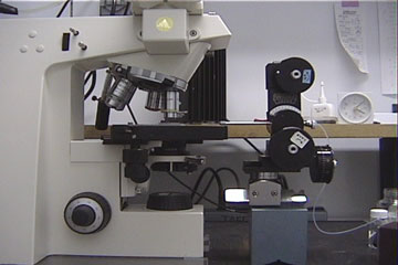
The equipment needed for microinjection is listed in the second part of this manual. The major items are an upright microscope, a micromanipulator, and a horizontal micropipette puller. You also need a microinjection syringe and micropipette holder, attached to each other with a piece of teflon tubing. This assembly is filled with silicon oil (or Fluorinert). The micropipette holder is held by the micromanipulator, and the syringe is held on a magnetic base.To avoid vibration, it is essential that the microscope as well as the micromanipulator are firmly attached to a heavy metal plate. The plate should be positioned on a solid table or bench, supported with 1-2" diameter rubber stoppers at each corner. The microscope can be attached with a glue gun, which does no harm to the microscope. Glue gun to the solid metal of the microscope, not the rubber feet. Place plexiglass or wood strips between the microscope and the metal plate to adjust the height with respect to the micromanipulator, and to avoid supporting the microscope on its rubber feet. The micromanipulator can be attached by way of a magnetic base. The microinjection syringe apparatus can be attached to the same plate by way of the magnetic base.
The microscope should be mounted with the front of the stage facing to the right, facing the micromanipulator. The head of microscope (the part with the eyepieces) should be rotated 90°, such that it faces the front of the table. To the right of the manipulator, attach a second magnetic base which holds the injection syringe (see details in equipment section).
Finally, check that everything is level, using a small "bubble" level. Check the table, the steel plate and the microscope stage. Sometimes you will find that even with the steel plate level, the microscope stage is not. This is a common problem with Zeiss Axioskops. To fix this, you can insert a shim where the stage is mounted to the microscope body. Alternatively, for a "quick fix", you can tilt the microinjection slide slightly, by lifting its front edge (a few tenths of a mm) such that it is not resting flat on the stage but is still held securely by the stage slide holder.
Picture of final set up.
2. Cleaning coverslips.
b. Prepare a dilute solution of detergent in hot water (a pinch
of Alconox in ~200 ml).
c. Using a fine forceps, drop individual coverslip (#1 1/2, 22 x
22 mm square) into the detergent solution. Put in half of one box
of coverslips. Let sit 15-30 min.
d. Attach the coverslip washer to the cold tap water line and fill
with water. Remove the lid, and using a fine forceps, transfer the
individual coverslips into the water in the washing tube. Put the
lid on, start the tap water running, and shake gently to
redistribute the coverslips.
e. Let tap water run through the washer for 1 hour, shaking
occasionally.
f. Transfer the input tubing to the deionized water line and let
1-2 gallons of water run through, while shaking gently.
g. Using a fine forceps, transfer the coverslips individually to a
jar containing 85% EtOH, 15% H2O for storage.
h. Before use, wipe the EtOH from the coverslip using a
kimwipe.
3. Making micropipets.
Using a 10 µl Hamilton syringe inserted from the back of the pipet, deposit ~1 µl of Hg so that it forms a bead in the region where the pipet begins to taper. You will later push the Hg to the tip of the pipet under microscopic observation.
4. Obtaining and handling starfish oocytes.
We will use oocytes from the bat star, Asterina miniata, obtained from the Pacific Ocean. The starfish species from the Woods Hole area, Asterias forbesi and Asterias vulgaris may also be tested. Female and male starfish cannot be distinguished externally. Sex can be determined by taking a sample with a 3 mm sample corer from Fine Science Tools, or a small cork borer. Push the sample corer through the dorsal surface of the arm. Alternatively, you can cut a slit between the arms with a razor blade. Ovaries are orange and testes are white. Ovaries or testes are located along the length of each arm.a. Follicle free immature oocytes.
b. Mature eggs.
To cause the oocytes to resume meiosis, and to undergo other changes necessary for normal fertilization ("oocyte maturation"), use the hormone 1 methyladenine (1-MA). From a frozen 10 µM stock solution in sea water, make a 1 µM solution of 1-MA. This will cause nuclear envelope breakdown (germinal vesicle breakdown = GVBD) to occur about 20-30 min later (at 18-22 °C). 10-15 min after that the oocytes will have reached first meiotic metaphase, where they remain until about 60 min after GVBD, when the first meiotic division occurs. Oocytes at first metaphase are referred to as "mature eggs". For optimal fertilization, insemination should be performed at this stage. After the oocytes pass the first meiotic division, they will continue on to complete both meiotic divisions. Oocytes that have proceeded beyond the first meiotic division are referred to as "overmature", because they will become polyspermic if inseminated. However, for the purpose of observing fertilization envelope elevation in response to IP3 injection, oocytes at any stage beyond GVBD can be used. Note that immature oocytes will not undergo normal Ca release and fertilization envelope elevation in response to IP3 injection.
An alternative way to obtain mature eggs is to collect the ovary in natural sea water, clip it in pieces, and apply 1 mM 1-MA directly to the ovary fragments. This will cause the ovary to spawn eggs at first metaphase, within about 30-60 min.
B. Preparation of the microinjection slide
1. Initial assembly
a. Apply silicon grease to both sides of the U-shaped cut-out of the plastic support slide, so that coverslips can be attached to both sides. Attach the bottom coverslip, flush with the front of the support slide.
A single piece of double stick tape produces a space of about 100 µm thick (good for most sea urchin or sand dollar eggs); two pieces of tape produce a space about 200 µm thick (good for many starfish eggs). The distance between the edge of the small coverslip and the tape can be varied, depending on the particular use. If sperm are to be added, it is best to keep the egg chamber shallow (~400 µm for starfish eggs), since sperm do not swim well between the coverslips. Several chambers may be assembled and stored. The plastic strips from slide boxes make convenient storage racks.
2. Loading eggs into the chambers
3. Final assembly
4. Observation of the preparation
5. Preparation of the loading capillary
Now apply wax to the other end of the capillary to seal it. Push the end of the capillary into a dish containing "valap" (see supply list). Be careful not to expel the injection solution and oil. After this, wipe the oil off the outside of the capillary with a Kimwipe. Apply a dab of valap to the center of the capillary and attach it to one side of the top coverslip of the injection slide. Repeat the procedure to prepare a control capillary (buffer only, no IP3). Attach the control capillary to the other side of the top coverslip.
The final slide should look like this:
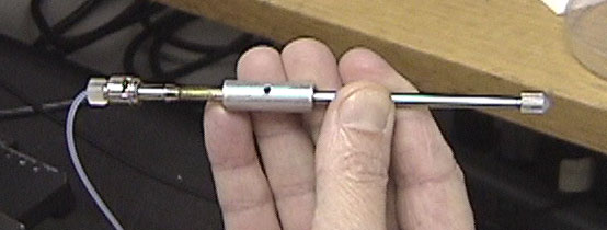
1. Mount the micropipette in the microinstrument holder
If the pipet breaks in the holder, unscrew the cap, remove the front brass collar, then pull out the silicon tubing and back brass collar using a syringe needle (~20 gauge). Clean off all glass fragments carefully, and flush through some oil to clean inside the tube. If the silicon tubing is frayed, put in a new piece. To do this, first insert the back brass collar. Then insert a long piece of tubing (about 1-2"), and cut off flush with the front of the holder. Insert the front brass collar into the cap, and screw on the cap.
Check that the pipet is parallel to the surface of the microscope stage. If not, adjust the micromanipulator.
2. Break off the tip of the micropipet
3. Bring the mercury to the tip of the pipet
4. Calibrate the micropipet
First you need to bring the pipet into the chamber, between the coverslips. Move the injection pipet away from the slide. Focus on the edge of an egg in the chamber. Then move the slide out of the field of view. Move the pipet into view and focus on the tip. Now turn the SM-20 micromanipulator 1-1/4 turns clockwise. This lowers the pipet tip ~60 µm, compensating for the difference in focussing through glass and water (to see the egg) and focussing through air (to see the pipet tip). Now move the pipet out of the field of view, and bring the egg into view. Slowly advance the pipet to the egg. When both pipet and egg are in view under the coverslip, adjust the vertical control on the micromanipulator to bring the pipet tip to the same focus as the edge of the egg.
Now that the pipet is in the chamber, expel oil. Measure the diameter of the oil drop and determine the volume (see attached table). For this IP3 injection exercise, we want to make a 1% volume injection. If the oil drop volume is not 1% of the volume of the egg, go back to the loading capillary and try again with a different length of oil. Adjust the amount of oil taken into the pipet until the volume is about 1% of the volume of the egg. For injections with this pipet, draw up the solution to the value of h determined in this calibration.
5. Load injection solution and oil into the pipet
6. Bring the pipet tip close to the egg
7. INJECT!
Observe the egg to determine if a normal fertilization envelope elevates, and to be sure that the egg is not damaged. Vacuoles in the cytoplasm or lysis at the injection site indicate damage. Do a control injection (buffer only, no IP3) to be sure the injection procedure is not causing envelope elevation. Sometimes a control injection will cause a local elevation of a fertilization envelope at the injection site. If this happens, try using a smaller pipet tip and performing the injection more delicately.
8. Calibration
![]()
|
(um) |
(pl) |
(um) |
(pl) |
|
|
|
|
|
|
|
|
|
|
|
|
|
|
|
|
|
|
|
|
|
|
|
|
|
|
|
|
|
|
|
|
|
|
|
|
|
|
|
|
|
|
|
|
|
|
|
|
|
|
|
|
|
|
|
|
|
|
|
|
|
|
|
|
|
|
|
|
|
|
|
|
|
|
|
|
|
|
|
|
|
|
|
|
|
|
|
|
|
|
|
|
|
|
|
|
|
|
|
|
|
|
|
|
|
|
|
|
|
|
|
|
|
|
|
|
|
|
|
|
|
|
|
|
|
|
|
|
|
|
|
|
|
|
|
|
|
|
|
|
|
|
|
|
|
|
|
|
|
|
|
|
|
|
|
|
E. MICROINJECTION OF FROG
EGGS
(Contributed by Linda Runft:
<runft@sun.uchc.edu>)
1. Introduction
Eggs from the African clawed frog, Xenopus laevis, provide a well-known system for studying fertilization and the later developmental events of vertebrate embryogenesis. Injecting unfertilized, mature frog eggs can be difficult, however, as these eggs can show fertilization-like responses when pricked, due to Ca2+ entry at the injection site. To inject mature eggs without causing artificial activation, we put eggs in a low Ca2+ bath solution (1.7 µM free Ca2+ and 10 mM MgCl2) and use finely tapered micropipets with a tip diameter of <4 µm. Both the low Ca2+ and the high ionic strength of the bath solution help to prevent artificial activation (Wangh, 1989, J. Cell Sci., 93: 1-8). The high Mg2+ may also be beneficial. We perform all mature frog egg injections at 18°C as temperature may be another important variable. For eggs matured in vitro, the time of injection in relation to the time of germinal vesicle breakdown (GVBD) is critical (see 3c below).By using the procedure described below, we find that up to 3 hours after injection (~3 1/2 hours after obtaining the eggs) close to 100% of the eggs are fertilizable.
2. Obtaining and handling frog eggs
The methods described below are useful for both jelly-intact frog eggs matured in vivo, and jelly- free frog eggs matured in vitro. In experiments where fluorescent dyes are injected into eggs, we use albino eggs to avoid absorbance of the dye fluorescence by the pigment found in the animal hemisphere of wildtype eggs.a. Frog eggs matured in vitro
Oocytes are obtained using standard techniques (Gallo et al., 1995, J. Cell Biol. 130: 275-284). Mature the oocytes by incubating them in 1µg/ml progesterone for 7-10 hours at 18°C. In our lab, we add progesterone to the oocytes using an automated dispenser, the "Early Morning Technician", consisting of a timer-controlled solenoid pinch valve (see Frog and Frog Supplies). Maturation in wildtype, pigmented frog oocytes is marked by the appearance of a white spot in the pigment of the animal hemisphere. Since albino oocytes contain no pigment in their animal hemisphere, the appearance of a "white spot" cannot be used as an indication of oocyte maturation. However, using a stereoscope and oblique illumination, a light gray spot, 300-400 µm in diameter, can sometimes be observed at the animal pole of immature albino oocytes. After 7-10 hours in progesterone, a smaller (~100-200 µm in diameter), dark spot is visible at the animal pole.
b. Frog eggs matured in vivo
Inject an adult female frog with 50 I.U. pregnant mare serum gonadotropin into the dorsal lymph sac followed 30 hours later with 700 I.U. human chorionic gonadotropin (HCG) (these hormones are available from Sigma). Mature eggs can be repeatedly squeezed from the frog from ~8 to 18 hours after the HCG injection.
3. Injection slide
a. Slide assembly
Cut a glass slide to 21 X 25 mm. Using silicon grease, attach this glass slide to the underside of a plastic support slide that has a U-shaped cut-out (same as described in "Microinjection Equipment and Supplies" in the starfish methods). Attach a piece of polyethylene 200 tubing (1.4 mm in diameter) on the glass slide with "tackiwax" (the piece of wax should have a rice grain size and shape). The tubing should be ~12 mm in length and be positioned in the U-shaped cut out about 3/4 of the way back from the front edge of the glass slide (see picture). Melt the wax by putting the tip of a fine soldering iron directly on the wax.
b. Preparation of the loading capillary
See "Preparation of the microinjection slide" in the starfish methods. We usually make the loading capillary from a piece of capillary tubing with an inner diameter of 0.6 mm. After loading the capillary with the silicon oil and injection solution, place the capillary to one side of the U- shaped cut out on the injection slide (see picture).
c. Placing eggs on the slide
Squeeze eggs in small piles (~15-30 eggs/ pile) from an ovulating frog onto a petri dish. Using forceps, gently lift up an egg by its jelly and place it against the polyethylene tubing on the microinjection slide. The jelly should secure the egg against the tubing. About 4 eggs easily fit on one slide. Cover the eggs with 1.7 µM Ca2+, 10 mM Mg2+ 1X MR (see recipe in Frog and Frog Supplies). Check the eggs with a stereoscope to make sure they haven't activated. Look for the elevation of the vitelline envelope as an indication of activation. In wildtype eggs, cortical contraction of the pigment in the animal hemisphere also indicates activation.
If eggs were matured in vitro, wash the matured eggs briefly in 1.7 µM Ca2+, 10 mM Mg2+ 1X MR. Then, using a fire polished wide mouth pasteur pipet, place the eggs against the polyethylene tubing on an injection slide already filled with the low Ca2+ MR. Be careful moving these slides around as the eggs will not be firmly attached to the tubing. Because eggs matured in vitro are more likely to activate at > 3 hours after GVBD, we inject these eggs < 3 hours after GVBD as a further precaution against artificial activation during microinjection.
4. Injection procedure
Observe the injections using a 5X objective on an upright Zeiss Axioskop with a micrometer reticle in the eyepiece. Perform all injections at 18°C.a. Preparation and mounting of the microinjection pipet
See "Making micropipetes" and "Injection" in the starfish methods. Make the micropipets from 1 mm O.D., 0.8 mm I.D. glass capillaries using a horizontal puller to produce a long taper. Using a Hamilton syringe, place a drop of mercury (~1 µl) in the micropipet at the point where it begins to taper. The mercury will permit controlled injections of precisely defined volumes. Insert the micropipet into a microinstrument holder connected with teflon tubing to a 2 ml micrometer syringe filled with fluorocarbon oil (FC-70).
b. Break micropipet tip and advance the mercury
Bring the edge of the loading capillary into view using a 5X, 0.15 N.A. Plan Neofluar objective. Using the micromanipulator horizontal control, bring the micropipet into view and focus it using the micromanipulator vertical control. Switch to the 20X objective and adjust the focus so you can see the concave edge of the loading capillary. If needed, refocus the micropipet using the micomanipulator controls. Slowly bring the micropipet tip to the upper edge of the loading capillary. Gently touch the micropipet tip to the edge of the loading capillary to break it. You want the diameter of the broken tip to be 3-4 µm. At 20 X, each small division of the eyepiece micrometer reticle is 5 µm. You may need to touch the micropipet tip to the edge of the loading capillary several times to get a 3-4 µm tip. A tip diameter smaller than 3 µm will make the micropipet difficult to load and a tip diameter larger than 4 µm can damage the egg during the injection procedure.
Switch to the 5X objective. Advance the micrometer syringe until the mercury in the micropipet starts to move forward. The mercury should travel to within a few µm of the micropipet tip. (It isn't necessary to bring the mercury all the way to the end.)
c. Fill the micropipet
At 5X, move the micropipet into the loading capillary using the stage controls. Draw up a small amount of silicon oil into the micropipet. (This oil will separate the mercury from the injection solution). Then move the micropipet into the injection solution. The total volume of a frog egg is about 1µl, so for example, a 5% injection means you want to inject 50 nl of injection solution into the frog egg. The volume of injection solution drawn into the micropipet for each injection is calibrated by measuring the decrease in the length of the column of injection solution in the loading capillary. The volume is determined using the equation : V=(p) (r)2 (h). At 5X, 50 nl is equal to the volume contained in a 180 µm long column in a 0.6 mm inner diameter loading capillary [V=(p) [(0.3mm)(0.3mm)] (0.18)]. At 5X, each smallest micrometer division equals 20 µM. Therefore, to load 50 nl of solution into the micropipet at 5X, apply suction causing injection solution to enter the micropipet until 9 micrometer divisions worth of solution has been removed from the loading capillary.
After loading the micropipet with the injection solution, move the micropipet tip back into the silicon oil. Draw up a small cap of oil (to protect the injection solution). Drawing up the oil cap may be hard to do. While applying suction, try carefully moving the micropipet back and forth in the oil using the stage controls. After the oil cap is loaded, adjust the micrometer syringe so there is no excess suction or pressure and then move the micropipet out of the loading capillary.
d. Injection of the frog egg
Perform the following directions at 18°C using a 5X, 0.15 N.A. Plan Neofluar objective. Move the micropipet out of the field of view using the micromanipulator controls. Bring the injection chamber into the field of view and focus on the egg you want to inject. Make sure the edge of the egg is in sharp focus. Move the injection slide out of the field of view and bring the micropipet back into the field of view. Focus the micropipet using the micromanipulator controls. Now turn the vertical micromanipulator control ~8 turns clockwise to lower the pipet. Lowering the micropipet will allow you to see it through the media on the injection slide. Slowly bring the injection slide into view and, using the stage controls, advance the micropipet through the low Ca2+ media to the egg. (You may have to adjust the micrometer syringe to apply a small amount pressure to keep the low Ca2+ media from entering the micropipet).
When both the pipet and egg are in view, adjust the micromanipulator controls to bring the micropipet tip into sharp focus. The edge of the egg should also be in sharp focus. Bring the micropipet up to the edge of the egg at its equator. Push the micropipet tip through the vitelline layer, then through the plasma membrane. The pipet will "pop" once through the vitelline layer and then once through the plasma membrane. (The needle will enter jelly free eggs matured in vitro more smoothly than eggs matured in vivo). If you're not sure if the needle is in the egg cytoplasm, pull the needle back a little and if a cone of cytoplasm pulls back with the needle then you're in! Once inside the egg, adjust the pipet to relieve the stretch on the membrane so the edge of the egg is smooth. Turn the micrometer syringe to expel the oil cap and injection solution. It will take about 10-15 sec for all the injection solution to enter the egg. Stop the injection when you see the interface between the injection solution and back volume of oil. Gently withdraw the pipet from the egg. Check to make sure the egg hasn't activated. Use each microinjection pipet only once.
After injecting jelly intact eggs, change the media on the slide to 1/3X MR (see media recipe in Frog and Frog Supplies). After injecting jelly free eggs, transfer the eggs, using a wide mouth pipet, from the slide to a 2% agarose layered petri dish containing 1/3X MR. Let the eggs incubate at 18°C in 1/3X MR to allow time for the injected substance to diffuse throughout the egg cytoplasm. For IgG (150 kDa), the time required is ~3 hours (as determined by observation of fluorescein-labelled IgG).
5. In vitro fertilization
Mince 1 testis in 400 µl 1/3 X MR. Dilute this concentrated sperm suspension 1:10 in 1/3X MR. Prepare 70 µl aliquots of the 1:10 sperm suspension and store them on ice (pipet the sperm using a wide orifice tip). Remove the 1/3X MR from the slide containing the injected, jelly intact eggs. Dribble 70 µl of the sperm susension directly on the eggs. It takes about 5-12 min after insemination for eggs to activate. Activation is characterized by a rise in intracellular calcium and by the elevation of the vitelline layer to form the fertilization envelope.
1. Upright microscope. A Zeiss standard or Axioskop or similar microscope works well. You can use a microscope with a fixed stage, but a standard microscope where the stage moves up and down to focus, works just as well or better. There must be a mechanical stage for X-Y movement. Ideally, the stage should have the x-y controls on the left side. (Controls are usually on the right side, but left hand stages are available, or the stage can be changed from right to left by a machinist). A 10x, 16x, or 20x objective should be used.
2. Micromanipulator. A Narishige SM-20 works well. A Leitz manipulator is also very good. The manipulator must have fine controls for X, Y, and Z movements. It must be mounted securely, preferably with a magnetic base. The magnetic base from Flexbar works well; to attach the manipulator to the magnetic base, have a machinist make a small aluminum bar.
The manipulator can be ordered directly from Japan:
Narishige Scientific Instruments Laboratory
27-9 Minamikarasuyama 4-chome
Setagaya-ku Tokyo, 157 Japan
Fax: 81-3-3308-2005
contact person: K. Sugita, Export Division (send a FAX)
Model SM-20: $4,199 (5/97) plus shipping and customs duty. Specify: for right hand use (unless you prefer left). (Right and left-handed manipulators are easily interconvertible: loosen screw under plate on the upper X-Y control. Slide plate off and rotate 180 degrees. Slide plate back on and turn knob until screw will come up into the groove. Tighten screw.
This manipulator is much more expensive if ordered from a U.S. distributor. The Japanese company provides excellent service; you can ship back the manipulator if service is needed. Contact Mr. Sugita.
The magnetic base can be ordered from:
Flexbar Machine Corp.
250 Gibbs Road
Islandia, NY 11722
800-879-7575
http://www.flexbar.comModel 11002: $86 (1/95)
3. Micropipette puller. An Industrial Science Associates M-1 puller works well. This company is no longer in business, but neurophysiology labs often have these pullers, and they are often no longer in use. Alternatively, a similar puller can be ordered from Narishige, Model PN-3: $2245 (1/95). Have the puller set by the manufacturer for use with 1.0 mm glass (not critical, this is easily adjustable).
Also get some 6 mm wide x 24.5 mm long heating elements (wider than the standard 2 mm heating element). These should be made of 90% platinum, and 10% rhodium. The thickness should be .001 inch (.002 inch is probably ok). USE OF A WIDE HEATING ELEMENT IS ESSENTIAL FOR MAKING PIPETS WITH A GOOD SHAPE. Unfortunately, Narishige does not sell these, and there is currently no source of the pre-made filaments. However, it is possible to buy the foil and make them yourself. For this purpose, it is most convenient to have a die for shaping the filament. Contact Laurinda Jaffe (ljaffe@cortex.uchc.edu) if you want information on the die. To obtain the foil, there are several possible sources:
Regina McNutty. 25-44 163 St., Flushing, NY 11358, 718-746-1519 (phone). This is the former owner of Industrial Science Associates. She has some of this foil, and is willing to provide it free (a strip of 6 mm wide ribbon), if you write her a letter.Sutter Instrument Company. 40 Leveroni Ct., Novato, CA 94949, 415-883-0128 (phone), 415-883-0572 (FAX). Sutter sells 90% platinum/ 10% iridium foil, that should be fine for the purpose. It is sold as a small sheet, 18 mm X 75 mm X.002 inches (FS-1875, cost $90). You can cut it with a paper cutter or scissors.
Alternatively, if you are very serious about this, or want to go into business making these filaments for the microinjectors of the world, you can buy a supply of foil from a precious metal dealer, made to your specifications. One supplier is:
Sigmond Cohn, 121 S. Columbia Ave., Mt. Vernon, NY 10553, 914-664-5300 (phone). They can make a ribbon with the desired composition and dimensions, but they have a minimum order of .26 oz = $731 at current metal prices. Also, they may or may not be willing to do it, since rhodium is bad for their machines.
One final supplier, who we have not yet contacted, but who may have this material, is:
Goodfellow Corp., 800 Lancaster Avenue, Berwyn, PA 19312-1780, 610-640-1612 or 800-821-2870 (phone).
4. Air Conditioner Starfish embryos (A. miniata) do not develop normally at room temperature (22 - 24 oC) and require temperatures below 20 oC. Also, in general, injection damage problems are less at cooler temperatures. Cooler temperatures are not absolutely essential for the IP3 exercise described here though, because maturation and IP3 induced Ca release seem to occur normally at room temperature. For experiments that require cooling, it is possible either to cool the entire room, or to blow cool air over the microscope stage and use an incubator for storing the eggs and embryos. To cool the room, or to blow cool air over the stage, a KoldWave is convenient - this is a water cooled air conditioner. Another way to direct cool air over the microscope stage is to connect a piece of dryer duct tubing from an airconditioner that may be built in to the room. Lead the dryer duct tubing to a position near the stage. A Koolatron (a small peltier cooler for drinks) makes a convenient and inexpensive incubator, if operated with an adjustable DC power supply (see below).
For a supplier of Koldwave airconditioners, contact:
Koldwave Division
Heat Exchangers, Inc.
8100 N. Monticello
Skokie, IL 60076
708-679-0300
Cost is about $1300-2000, depending on the model.
A Koolatron cooler can be ordered from:
Koolatron
1 Mill Street
Batavia, N.Y. 14020
800-869-6996
Model P9, Traveller II portable cooler, $80 (2/98)This cooler is normally operated with a 12 volt car battery, to bring the temperature to about 4oC. For use as an incubator at about 18-20oC, it should be operated with a lower voltage (about 2-3 volts). For this purpose, use a DC power supply from EPSCO:
EPSCO, Inc.
1115 Hilltop Drive
Itasca, IL 60143
800-294-8585Model EC-2, $199.50 (1/98)
Note that this power supply runs both the Peltier cooling unit and the fan. At this voltage, the fan runs somewhat slower than it should, but this is workable. If you want a really perfect incubator, replace the Koolatron fan with a small 120 volt fan from an electronics supplier, and plug in the fan separately. (With long term use at 3 volts, the Koolatron fan may eventually fail to work.)
Electronic thermometer
To use the Koolatron incubator, you also need a small electronic thermometer, to put inside the box. Adjust the power supply voltage to achieve the desired temperature. Inexpensive electronic thermometers are sold by:
Edmund Scientific Co.
101 East Gloucester Pike
Barrington, N.J. 08007
609-573-6250Model A37,396, $26.95 (1997)
Get one of these for your microscope stage as well! Too high a temperature is another major cause of microinjection failure! Equipment in a small lab can heat the room well above normal temperature, so monitoring microscope temperature is a good idea.
5. Stereoscope with a reticle. This is not essential, particularly if you are under 40, but is very useful for assembling microinjection chambers.
1. Eyepiece micrometer reticle. For the Zeiss standard microscope, you need a 19 mm diameter disc. For the Zeiss Axioskop, you need a 22 or 26 mm disc, depending on the type of eyepiece. (Other microscopes may require slightly larger or smaller discs). The reticle should have a 10-12 mm scale (12 mm is better), divided in 100-120 divisions. Reticles can be ordered from:
Carl Zeiss Inc.
Microscope Division
One Zeiss Drive
Thornwood, NY 10594
914-681-7800 or 800-892-0116or:
Klarmann Rulings Inc.
PO Box 4795
Manchester, NH 03108
603-424-2401
800-252-2401
KR-221 Microscope reticle, 12 mm in 120 parts, specify diameter of disc, $54 each (11/97)
2. Micrometer syringe. The Gilmont model S-1200 works well.
Gilmont Instruments, Inc.
28W092 Commercial Ave.
Barrington IL 60010-2392
1-800-962-7142Cat. no. GS-1200, $91
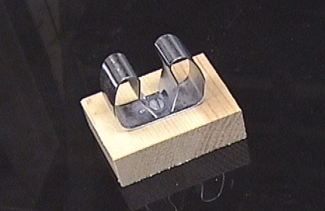
3. Magnetic stand for holding micrometer syringe.
Flexbar Machine Corp.
250 Gibbs Road
Islandia, NY 11722
800-879-7575
http://www.flexbar.comCat. no. 11004: $36
The stand comes with a post which is removed and replaced with a bolt, and a clamp made from a strip of 1/2" metal braid with a metal tab soldered on the end. Metal braid is available from electronics suppliers such as Newark. See picture
Another convenient way to attach the syringe to the magnetic base is with a metal hose clamp (a metal ring that tightens down with a screwdriver). Hose clamps are available in hardware stores.
4. Leica microinstrument holder
Kramer Scientific Corp.
5 Westchester Plaza
Elmsford, N.Y. 10523
(914) 345-6060 (phone)
(914) 345-2460Cat. no. 520145,
1 set of 3, $152 (4/97)Also order the following replacement parts for the microinstrument holder:
W832688 Tubing replacement* $10/yard
026-350-012-007 Brass collar replacement $1.55 each* specify silicon rubber tubing. Leica also supplies Tygon tubing as a replacement, but this does not work well.
To hold the microinstrument holder in the SM-20 micromanipulator, have a machinist make a metal collar.
5. Syringe needle adapter.
Thomas Scientific
P.O. Box 99
Swedesboro, N.J. 08085-0099
(800) 345-2100Cat. no. 8960-D59, $8 each (4/98)
Have a machinist attach the syringe needle adapter to the microinstrument holder.
You can do this yourself using silver solder (4% silver, 96% tin) and stainless steel soldering flux, available from:
Ed Mar Crystal and Jewelry Co., Inc.
710 Sansom Street
Philadelphia, PA 19106-3296
(215) 922-5469
Staybrite low temperature silver bearing solder, and flux ($6.75) (p. 229, catalog #54.452) (3/99)
Kester Solder (Chicago, IL) also makes this type of solder. Ordinary solder for electronics will not work for soldering brass and stainless steel. Before soldering, cut off the back of microinstrument holder and file it down to fit in the syringe needle adapter. Apply flux, heat the metal pieces with a soldering iron, and apply solder.
6. Teflon tubing with CTFE hub on both ends, 1-3 ft, 2 ft is best, but 1-3 ft is OK too, 20 gauge.
Scientific Commodities, Inc.
1799 Kiowa Avenue #107
Lake Havasu City, AZ 86403
800-331-7724Cat. No. BB635-02, pkg. of 3 = $33 (4/98) specify on order: 20 gauge and 24" length (custom order, 2-3 weeks)
or
Hamilton Company
P.O. Box 10030
Reno, Nevada 89502-4178
(800) 648-5950Cat. No. 86510, $16 each (min. order of 3)
You can also use polyethylene or teflon tubing, with cut off syringe needles pushed into the ends, for making the connections to the syringe and micro-instrument holder.
7. Steel plate 24" x 18" x 1/4" is good; larger is o.k., too. Steel plates can be obtained from a machine shop; a plate this size is about $50. It is supported on rubber stoppers to prevent vibration. The plate should sit on a solid table, preferably not a bench attached to the wall.
8. Plexiglas or Plywood boards. These are used to raise the microscope to the level of the micromanipulator. For a Zeiss standard or Axioskop microscope and a Narashige SM-20 manipulator mounted on a Flexbar base, the microscope needs to be raised about 3/8 - 1" above the surface to which the manipulator is attached.
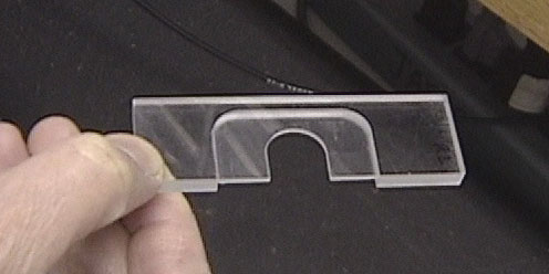
9. Microinjection chamber support slide. This can be machined from a 3" x 1" x 1/4" piece of plexiglas as shown:
Order from:
Bob Knudson,
Instrument Development Lab
Marine Biological Labs
Woods Hole, MA 02543
508-289-7478
rknudson@mbl.edu
(He has this design set up in his computerized milling machine. Cost ~$12-20 each depending on number ordered)
See Kishimoto (1986) for a simple alternative design that works very well. For some microscope condensors, it is better to use a thinner slide. Slides can also be made of stainless steel or aluminum.
10. Black plexiglas sheet (4" x 8" x 1/4") for a work surface; available from a machinist.
11. Diamond pencil
12. Pipetmen (P20 and P10)
13. Watchmaker's forceps (2)
14. Small scissors
15. Flexible clear plastic ruler (6")
16. Coverslip washer, made from a 50 ml polypropylene centrifuge tube, a 3' long piece of Tygon tubing (3/8" O.D., 1/4" I.D.) and a tubing connector (Cole Parmer type J-6288-10).
17. Glass or polyethylene jar, for storing coverslips in 85% EtOH.
18. Mouth pipet.
Mouth pipets, assembled with tubing, can be ordered from:
Drummond Scientific Company
P.O. Box 700
Broomall, PA 19008
800-523-7480Cat. # 2-000-000, aspirator tube, $1.10 each (4/98)
Note that it is best to order directly from Drummond; ordering through Fisher can result in a delay of several weeks.
Another supplier, if you prefer a flat rather than a round mouthpiece, is:
HPI Hospital Products
P.O. Box 162992
Altamonte Springs, FL 32716
800-447-0014Cat. # 1506P, white mouthpiece, pkg. of 12, $4.50 (4/98)
Cat. # 1501P, red mouthpiece pkg. of 12, $4.50
Cat. # 1503P, rubber tubing, pkg. of 12, $6.50
Cat. #1512 P, green adapter, pkg. of 12, $4.50
Another style of mouth pipet can be assembled by attaching a mouthpiece to a piece of intramedic polyethylene tubing (Clay Adams, PE-60, from Thomas Scientific). Attach the tubing to the mouthpiece as follows:
Attach a piece of glass tubing (0.8 mm O.D., 0.6 mm I.D., 100 mm length, see below) to the end of the polyethylene tubing.
19. Hamilton syringe, 10 ml. Hamilton #80360, Fisher Scientific 14-824-54A, $49 (4/98).
20. Glue gun. Hardware store (~$20).
1. Mercury Sigma or other chemical supply company. Another good source of clean mercury is to break a glass thermometer.
2. Silicon oil (100 centistokes) (From Sigma: dimethylpolysiloxane, DMPS-1C, 100g, $14.55). Don't use mineral oil in the micropipet; it is toxic to eggs.
3. Fluorinert oil, type FC-70 (Sigma F9880, 100 ml, $114) for filling tubing to syringe. Silicon oil can be used instead, and is 8X cheaper. (But don't mix with Fluorinert!) As far as we can tell so far, silicon oil is just as good, except that because it is more viscous, it tens to be a little messier.
4. Silicon high vacuum grease (for assembling injection slide).
5. Alconox detergent (for cleaning coverslips).
6. 85% EtOH (for storing coverslips).
7. Coverslips (No. 1/1/2 thickness, 22 mm square)
8. Double stick Scotch tape.
9. Valap (a 1:1:1 mixture of beeswax, vaseline and lanolin, melted together). Beeswax is sold by Fisher. Vaseline and lanolin can be purchased at the drugstore.
10. Sticky foam weatherstripping tape (to be mounted with double stick tape inside a 150 mm Petri dish). Can be purchased at the hardware store. You can also purchase a micropipette storage jar:
Cat. # E210 micropipette storage jar, micropipette O.D. 1.0 mm, $32 from:World Precision Instruments
175 Sarasota Center Blvd.
Sarasota, Florida 34240
941-371-1003
(4/98)
11. Glass tubing. For injection pipets, use pyrex glass with an outer diameter of 1.0 mm. The glass should have a thin wall (~0.1 mm) and should not contain a filament (commonly present in glass used for electrophysiology). 50 microliter "microcaps" from Drummond work very well. These are 1.0 mm in diameter.
Drummond Scientific Company
P.O. Box 700
Broomall, PA 19008
800-523-7480Cat. # 1-000-0500, $9 per vial of 100 (4/98)
Note that it is best to order directly from Drummond; ordering through Fisher can result in a delay of several weeks.
For mouth pipets and loading capillaries, get some slightly smaller tubing.
Cat # 9-000-1061-100 Custom Pyrex Tubing, 100 pieces per vial, O.D. 0.8 mm, I.D. 0.6 mm, length 100 mm, $13 per vial of 100 (from Drummond).
D. Starfish and starfish supplies
1. Starfish
Asterina miniata (also called Patiria miniata) are available from suppliers of marine animals in California. They generally have full grown oocytes between the beginning of May and the end of October. Animals collected in October can be kept in an aquarium at 15 °C for use during winter months. The following supplier provides Asterina:
Marinus, Inc.
1500 Pier C. St.
Long Beach, CA 90813
562-435-6522, George Kelly
marinebiol@msn.com
($3.50 each + shipping) (5/97)
Asterias forbesi, an Atlantic species available at Woods Hole in the summer, can also be used.
2. Sample corer, 3.0 mm
Fine Science Tools
373-G Vintage Park Drive
Foster City, CA 94404-1139
800 521 2109
http://www.finescience.com
cat. # 18035-03, $39.50
3. Artificial Sea Water (MBL formulation; different artificial sea waters vary)
|
grams/liter |
concentration (mM) |
|
NaCl |
25.5 |
437 |
|
KCl |
0.67 |
9.0 |
|
MgCl2 6H2O |
4.7 |
22.9 |
|
MgSO4 7H2O |
6.3 |
25.5 |
|
CaCl2 2H2O |
1.35 |
9.3 |
|
NaHCO3 |
0.18 |
2.1 |
pH = 8, adjust with NaOH
For Calcium Free Sea Water, leave out the Ca
4. Other supplies for working with starfish oocytes
razor blades
small dissecting scissors
small blunt forceps (curved Graeffe forceps from Fine Science Tools,
model 11051-10, $41.50, are nice)
small beakers (30 ml size, tall narrow beakers are best)
ice bucket
1-methyladenine (Sigma M-4876). Make aliquots of 10 µM in sea
water. Store at -20 C, keeps > 1 year. Use at 1 µM.
inositol 1,4,5 trisphosphate (Amersham RPN 2 or Calbiochem 407123,
100 mg, $64)
aspartic acid, monopotassium salt (Sigma A-9381)
Hepes (Sigma H-3375)
Natural sea water (from MBL)
a. FrogsXenopus laevis frogs (wildtype and albino) are purchased from NASCO.
NASCO
901 Janesville Ave.
Fort Atkinson, WI 53538-0901
1-920-563-2446We generally purchase 9+ cm female frogs and 6.25-7.5 cm male frogs. Frogs are housed in aquaria at 18-20 °C. Many different aquaria designs work well. We use large fiberglass tanks (5 feet by 3 feet, 1 foot deep) divided into three sections by two partitions. These tanks were obtained from the Marine Biological Laboratory in Woods Hole (retired marine aquaria). Contact Ed Enos in Marine Resources (508-289-7455) for information. We house about 10 frogs per section (30 frogs/tank). Above the frog tank is a shallow holding bin which holds the water used to change the frog tank water. A holding bin is used so the water can reach 18°C before it is drained down into the frog tank. We prepare the frog bath by adding 2.7 liters of a concentrated salt solution (40 g Tropic Marin salt/ liter distilled water) to 164 liters of distilled water in the frog tanks (the final osmolarity in the frog tank is ~20 mosm). Three times a week the frogs are fed Purina trout chow fish food (5-8 pellets/ frog) and their water is changed. Frogs can be ovulated all year long. After a frog is ovulated, we generally wait 3 months before injecting it again with HCG.
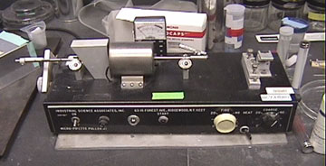
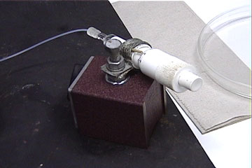
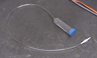
b. Early morning technician
Picture of the early morning technician
The early morning technician, designed by Ray Kado, provides a convenient means for applying progesterone to oocytes at inconvenient times. It consists of a reservoir of progesterone solution which is drained onto the oocytes using a timer-controlled solenoid pinch valve (see picture). The progesterone solution is held in a 30 ml syringe connected by way of a 13 gauge needle to a piece of silicon tubing. The tubing is threaded through the solenoid pinch valve. The pinch valve is connected to a 12 volt DC power supply which is controlled by a timer. The apparatus is assembled on a clamp stand. For a typical experiment, we place the oocytes in a 60 mm petri dish on a cushion of agarose (3 ml of 2% agarose made in 1X MR) in 8 ml of OR3 (media recipes below). We load the reservoir of the Early Morning Technician with 8 ml of 2 µg/ml progesterone in OR3. When the reservoir is released (at ~ 3:00 AM), the solutions mix, resulting in a final progesterone concentration of 1 µg/ml.
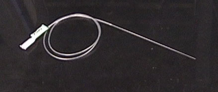
Solenoid pinch valve
Neptune Research Inc.
P.O. Box 6279
267 Fairfield Ave
West Caldwell, N.J. 07007-6279
Part # 225PO21-21 with #TBGM101 tubingpicture of pinch valve
EPSCO power supply
EPSCO Inc
1115 Hilltop Dr
Itasca, IL 60143
1-800-294-8585
cat # EC-2Timer to control 120 volt AC power to the EPSCO power supply.
A timer of the type used to control household lights works well (available in most hardware stores).
c. Other supplies for working with frog eggs
Polyethylene tubing used as a backstop on the injection slide
Clay Adams #PE-200
Fisher Scientific
Pittsburgh, PA.Firepolished, widemouthed pasteur pipets
Using a diamond pencil, etch a ring around a pasteur pipet about where it begins to taper. Break off the thin part of the pipet. Fire polish the broken end over a bunsen burner flame.2% agarose layered petri dishes
Mix 2g agarose (Sigma, St Louis, MO., cat# A-3768, type V: high gelling temperature) in 100 ml 1X or 1/3X MR. Boil in a microwave until the agarose is completely dissolved (alternate boiling with swirling). Pour about 1 ml into 35X10 mm petri dishes and 3 ml into a 60X15 mm petri dishes. Let the dishes cool and store at 4°C.1X MR (Modified Ringers for handling Xenopus oocytes)
100 mM NaCl, 1.8 mM KCl, 1 mM MgCl2, 2 mM CaCl2, 5 mM HEPES, pH 7.8. Use 1/3X MR for fertilization. Make these solutions from a 10X MR stock.OR3 (Ooctye Ringers 3, for culturing Xenopus oocytes).
50% Leibowitz medium from GIBCO, 15 mM HEPES, pH 7.2-7.4, 100 µg/ml gentamycin (order stock solutions from GIBCO).Progesterone (Sigma P-0130)
Make a 10 mg/ml stock in EtOH, good for a couple of weeks at room temperature. Add 2 µl to 20 ml OR3 to make 1 µg/ml solution.Purina Trout Chow fish food
Purina Mills Inc
PO Box 66812
St Louis, MO 63166-6812Tropic Marin salt
Marinus Inc
1500 Pier C St
Long Beach, CA 90813
(562) 435-6522100 ml of 1.7 µM free Ca2+, 10 mM Mg2+ 1X MR
Bring up to 100 ml with milli Q or distilled water
Stock
Amount added
Final concentration
1M NaCl
10 ml
100 mM NaCl
1M KCl
180 µl
1.8 mM KCl
1M MgCl2
1 ml
10 mM MgCl2
1M HEPES
500 µl
5.0 mM HEPES pH 7.0
1M CaCl2
150 µl
1.5 mM CaCl2
0.5 M EGTA
400 µl
2.0 mM EGTA
pH to 7.0 with NaOH
Concentration of free Ca2+ was calculated using the program "Free Calcium" available at: http://155.37.3.143/panda/injection/freeca.hqx
This manual was originally used in the MBL Embryology Course beginning in 1983 by Laurinda Jaffe. In 1996-7, it was brushed off, up-dated, re-coded, down-loaded, de-bugged and generally prepared for its grand debut on The Internet in the latter part of 1997. It is pretty much in a final form, but is still undergoing some revisions. Plans for a new section on mouse microinjection techniques are being considered. Please address microinjection questions to Laurinda Jaffe and web-related questions to Mark Terasaki.